Entities Definition
Organization Unit
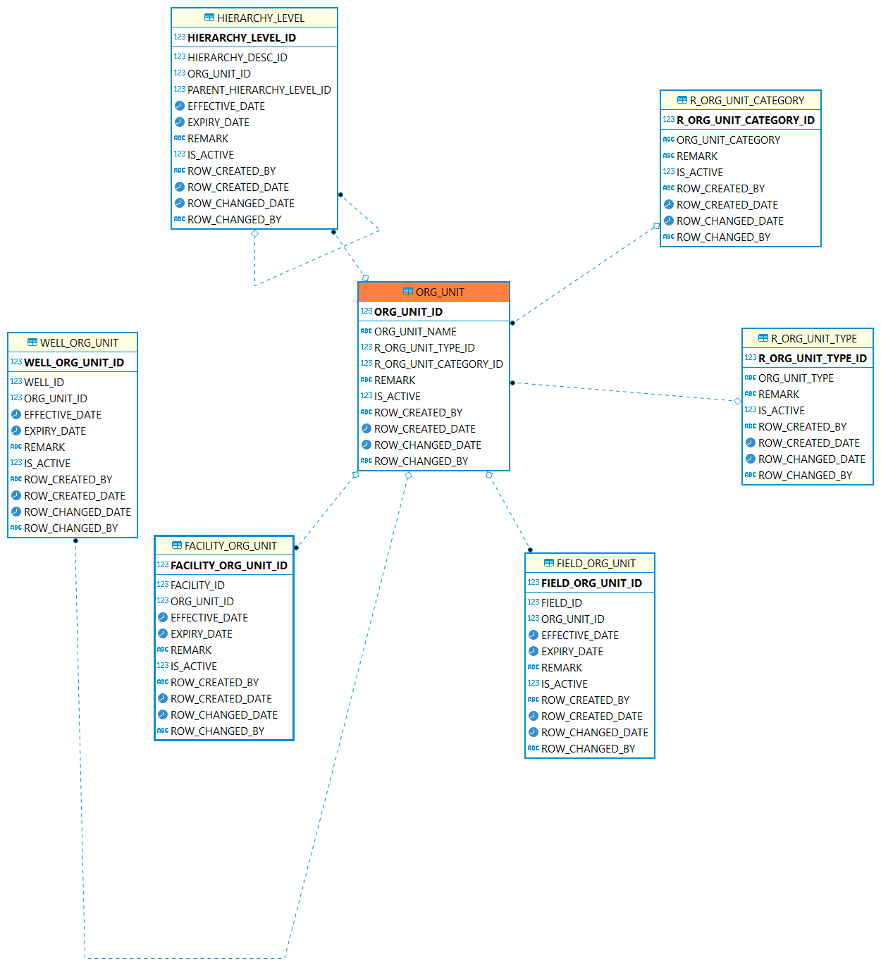
Organization Unit: Describes geographic areas, such as country, province, district etc. and the business unit, such as company, partners, and other parties.
| Table | Description |
|---|---|
The table is used to record the geographic and organizational area, such as country, state, province, company, 3rd partners instance etc. |
|
The reference type of organization unit. For example: country, state, province, company, 3rd partners. |
|
The reference type of organization unit. For example: Area Unit, Business Unit. |
|
This table is used to record the field historical relationship with org units. |
|
This table is used to record the facility historical relationship with org units. |
|
This table is used to record the well historical relationship with org units. |
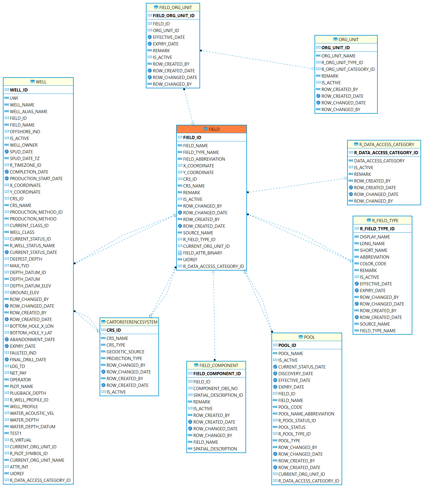
Field: A field is an area consisting of a single reservoir or multiple reservoirs all grouped on, or related to.
| Table | Description |
|---|---|
The table is used to record the geographic and organizational area, such as country, state, province, company, 3rd partners instance etc. |
|
A geographical area defined for administrative and legal purposes. The field name refers to the surface area, although at times it may refer to both the surface and the underground productive zones. |
|
This table is used to record the field historical relationship with org units. |
|
A reference table identifying the type of field. For example, regulatory or locally assigned. |
|
A coordinate reference system (CRS) refers to the way in which spatial data that represent the earth s surface (which is round / 3 dimensional) are flattened so that you can draw them on a 2-dimensional surface. For example, WGS 84, UTM. |
|
POOL/RESERVOIR: Represents a reservoir or a group of small tracts of land. Pool can have relationship with field. |
|
Well is drilled for a field. Well can have relationship with field. |
|
This table is used to capture the components of field. |
Formation
Formation: A body of rock, of significant and distinctive occurrence, distinguished from adjacent rock bodies on the basis of any one or more primary properties or attributes that rocks possess, such as mineral or fossil assemblages lithologic characteristics, environment and other natural occurrences. (In PPDM is Strat Unit)
Reservoir
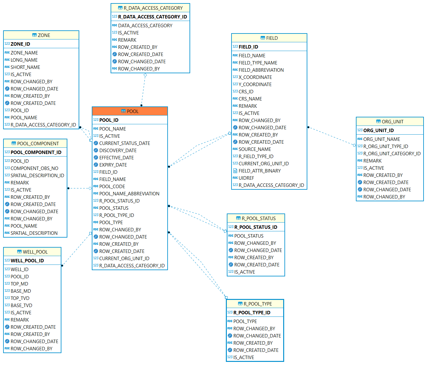
Reservoir: Defined as a storage space for fluids, reservoirs hold water or gas and hydrocarbons. (In PPDM Pool is used to represent reservoir.)
| Table | Description |
|---|---|
POOL/RESERVOIR: Represents a reservoir or a group of small tracts of land brought together for the granting of a well permit under applicable spacing rules. |
|
A reference table identifying the operational or legal status of the pool. |
|
A reference table identifying the type of pool. |
|
This table is used to capture the components of pool. |
|
The pools intersected by one well. |
|
Pool/Reservoir includes multiple zones. |
Zone
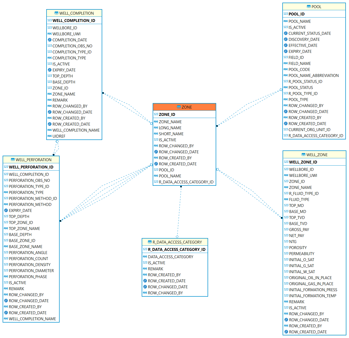
Zone: A zone may be a regular or irregular belt, layer, band, or strip of earth materials disposed horizontally, vertically, concentrically, or otherwise, and characterized as distinct from.
| Table | Description |
|---|---|
The ZONE table contains the name of a zone described in a field or reservoir. A zone may be a regular or irregular belt, layer. |
|
POOL/RESERVOIR: Represents a reservoir or a group of small tracts of land brought together for the granting of a well permit under applicable spacing rules. |
|
This table records the zone information a wellbore intersecting. Such as top/bottom depth, porosity etc. |
|
The Well Completion table identifies the completion activity in the wellbore. A completion interval should relate to a production zone. |
|
The Well Perforations table contains detailed intervals of completion. A perforation interval can relate to a production zone. |
Well
Well: A well is an excavation or structure created in the ground by digging, driving, or drilling to access liquid resources.
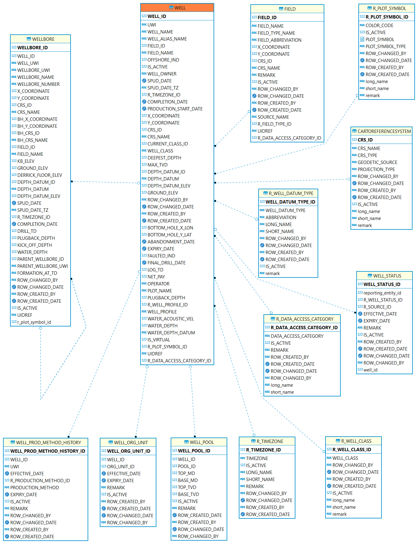
| Table | Description |
|---|---|
WELL: A well is the location on the surface of the earth or sea bed where the drill bit is planned to penetrate or does penetrate the earth to establish or rework a well. |
|
WELLBORE: A Wellbore is a path of drilled footage, from Well Origin (top/start) to a terminating point (bottom/end). |
|
The well is drilled for which field. |
|
The pools intersected by one well. |
|
This table is used to record the well historical relationship with org units. |
|
This table defines the status history of the well. |
|
Contains an historical account of the production method of the well. |
|
This reference table describes the classification of a well. This may include but is not restricted to the Lahee classification scheme. |
|
This reference table describes the icons used for different wells. |
|
A reference table identifying the type of point or horizontal surface used as an elevation reference for measurements in a well. Examples: Kelly bushing, ground, sea level. |
|
A valid list of time zones. |
|
Coordinate reference system (CRS). |
|
This reference table identifies the method of production. |
Wellbore
Wellbore: A Wellbore is a path of drilled footage, from top/start to a terminating point (bottom/end).
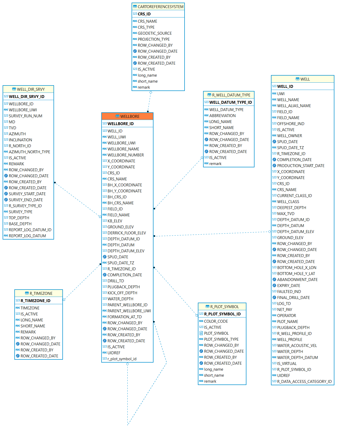
| Table | Description |
|---|---|
WELLBORE: A Wellbore is a path of drilled footage, from Well Origin (top/start) to a terminating point (bottom/end). |
|
The wellbore is for which well |
|
The binary data reference to represent an icon or picture of this wellbore. |
|
A reference table identifying the type of point or horizontal surface used as an elevation reference for measurements in a well. Examples: Kelly bushing, ground, sea level. |
|
A valid list of time zones. |
|
Coordinate reference system (CRS). |
|
The Well Directional Survey table contains header information about directional surveys which have been performed on a wellbore. This downhole survey charts the degree of departure of the wellbore from vertical and the direction of departure. Since many directional surveys can be conducted on a wellbore, the survey number is included as part of the primary key to uniquely identify the survey. |
Completion
Completion: Downhole completion, it refers to the portion of the well across the production or injection zone. One completion is a set of perforations.
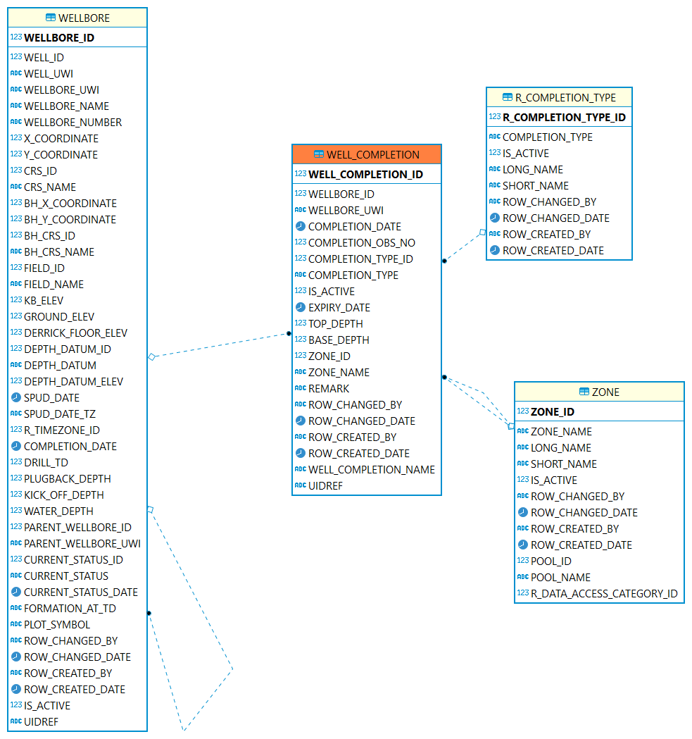
| Table | Description |
|---|---|
The Well Completion table identifies the completion activity in the wellbore. |
|
The completion is for which wellbore |
|
The type or method of well completion. |
|
The completion interval is for which zone. |
Perforation
Perforation: A perforation refers to a hole punched in the casing or liner of a well to connect it to the reservoir. Creating a channel between the pay zone and the wellbore to cause oil and gas to flow to the wellbore easily.
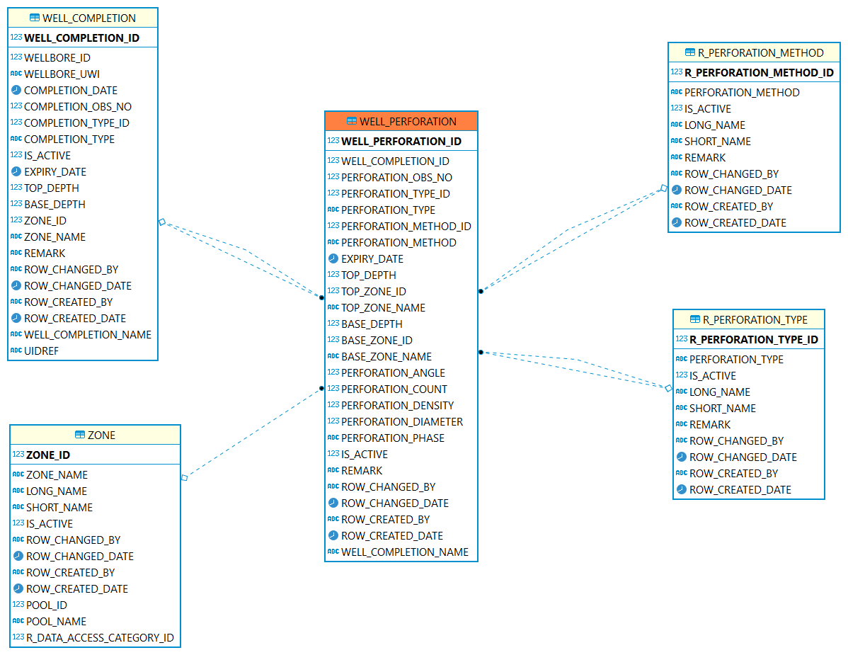
| Table | Description |
|---|---|
The Well Perforations table contains detailed perforation activity performed on a well. |
|
The perforation is for which completion interval. |
|
A reference table identifying the type of perforation method. For example bullet, jet or combination. |
|
Code identifying the type of opening the fluid entered through into the tubing (e.g., perforation, open hole, combination, etc.). |
|
The perforation interval is for which zone. |
Well Tubular
Well Tubular: The Well Tubular table contains information on the tubulars for the well. The tubulars can be tubing, casing or liners which are run into the well.
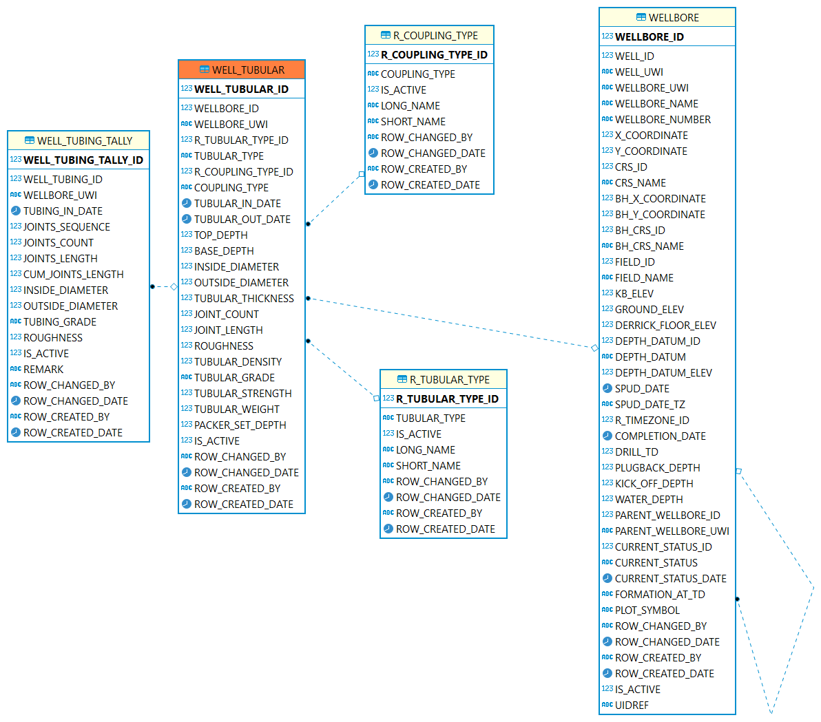
| Table | Description |
|---|---|
The Well Tubular table contains information on the tubulars for the well. |
|
The well tubular is installed in which wellbore. |
|
A list containing details of tubulars that have been prepared for running, or that have been retrieved from the wellbore. |
|
A short length of pipe used to connect two joints of casing. |
|
The particular type of tubular. |
Facility
Facility: A collection of surface equipment and meters which facilitate the production, injection or disposition of products
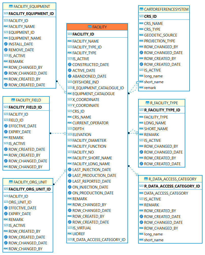
| Table | Description |
|---|---|
A collection of surface equipment and meters which facilitate the production, injection or disposition of products. |
|
A reference table identifying the codes classifying the facility according to its physical equipment or principal service performed. |
|
Coordinate reference system (CRS). |
|
The data access category. |
|
Cross reference table indicating which fields a facility is associated with. |
|
Record the facility historical relationship with org units |
Equipment
Equipment: Pieces of equipment that are real. May be any kind of equipment, such as meters, gauges, pump motor etc.
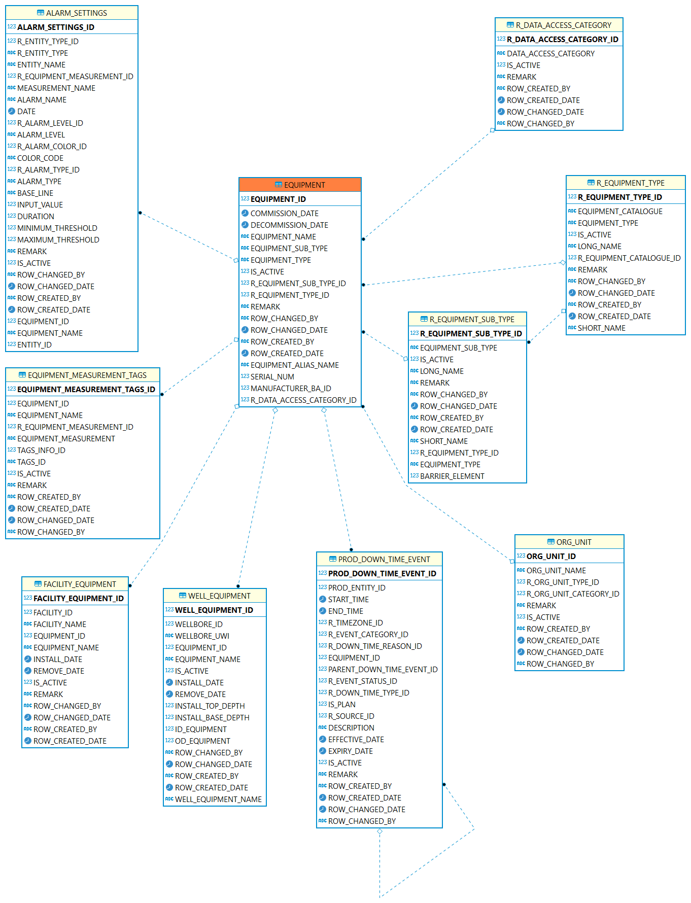
| Table | Description |
|---|---|
Use this table to describe pieces of equipment that are real. |
|
This table can be used to keep track of which equipment is occupying that facility. |
|
This table can be used to keep track of which equipment is occupying that wellbore. |
|
Use this table to list the types of equipment |
|
Use this table to list the sub types of equipment |
|
Which equipment is related to alarm setting. |
|
This table is used to clarify which tag is associated with which equipment measurement. |
|
Which equipment is related to a down time event. |
Flow Model
Flow Model: The flow model is used to describe the flow connections for the product be transported to a facility where it can be produced/treated, stored, processed, refined, or transferred for eventual sale. Below is showing a core structure of the flow model, which is made up of model,network,unit, port and connected node. More detailed information please refer to Flow Model chapter.FlowModel Introduction
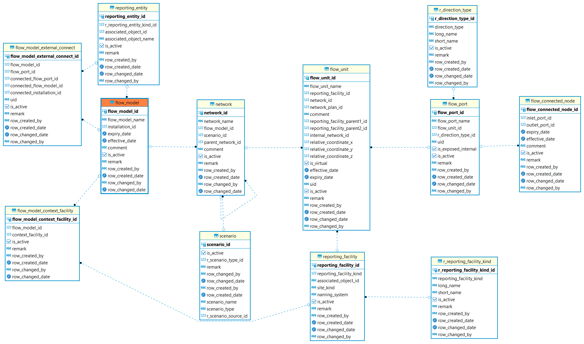
| Table | Description |
|---|---|
The non-contextual content of a product flow model data object. Model is a collection of networks. |
|
Identifies a entity this flow model represents for. |
|
Identifies a facility or a well instance. |
|
Identifies type is facility or well. |
|
Identifies the context facilities of the model. |
|
Defines the external port in another Product Flow Model to which an external port in this model is connected. |
|
The network represents the internal behavior of the model or a unit in another network and is a collection of connected units. |
|
Specify the scenario of the network. |
|
A flow unit is essentially a black box that can represent anything. |
|
Ports allow flow in or out of a unit. |
|
To specify Port direction is flowing in or out of a unit. |
|
Flow connected nodes are used to connect ports. |