Flow Model Data Model
Concept Model
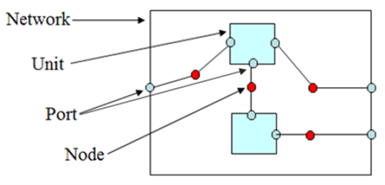
There are 5 levels for a flow model.
-
Model: collection of networks
-
Network: collection of connected units
-
Unit: black box with ports
-
Port: allows flow in or out
-
Node: allows ports to connect
The network represents the internal behavior of the model or a unit in another network and is a collection of connected units. A unit is essentially a black box that can represent anything. Ports allow flow in or out of a unit. Nodes are used to connect ports.
Core Structure
Below is the core structure diagram of one flow model.
-
Flow model is the top level. It is a collection of networks.
-
One or more networks can belong to one flow model.
-
Network can have its parent network.
-
Network is a collection of connected units.
-
Flow unit can represent anything. PDM recommends flow unit to be well or facility.
-
One flow unit represents one reporting facility.
-
Flow port allows fluid flow in and out of a unit. It has inlet and outlet direction.
-
Flow connected Nodes are used to connect flow ports. It has effective and expiry date.
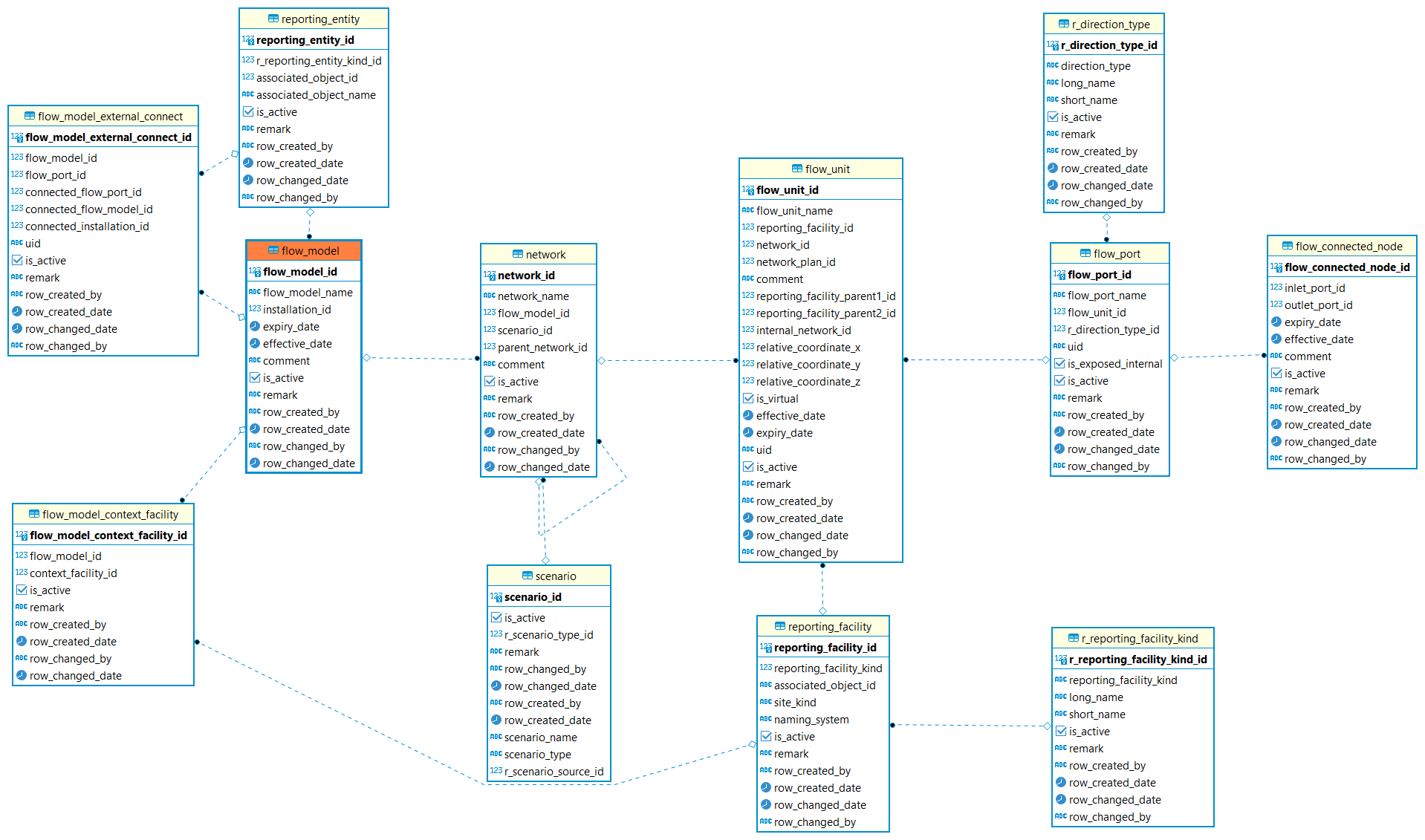
For model, it has effective date and expiry date to specify when this model is validated and terminated the validation. The existence time and minimum/maximum time is used for server query. There are context facilities can be related to one model. Once a model is created, user is able to define the external port, which is used to allow fluid flow in/out of with another product flow model. An external port should be connected to an external port with the opposite direction. The connected external port must be in another product flow model.
Network
-
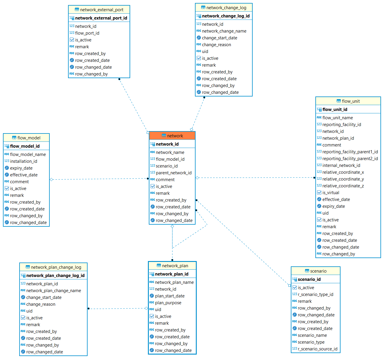
Network must under one model. one network can have its parent network.
-
Once a real network is created, the network_change_log table is used to document the changes occurred at a particular time. 3-The plan to extend an actual network is tracked in the product_flow_network_plan table.
-
Network_plan is used to record the network extend plan. It Documents that a change occurred at a particular time
-
Network_plan_change_log is used to document the changes occurred for this plan.
-
Network_external_port: An external port. This exposes an internal node for the purpose of allowing connections to the internal behavior of the network. Networks that represent a Flow Unit should always have external ports. If this network represents a Unit then the name of the external port must match the name of a port on the Unit (i.e., they are logically the same port).
Flow Unit
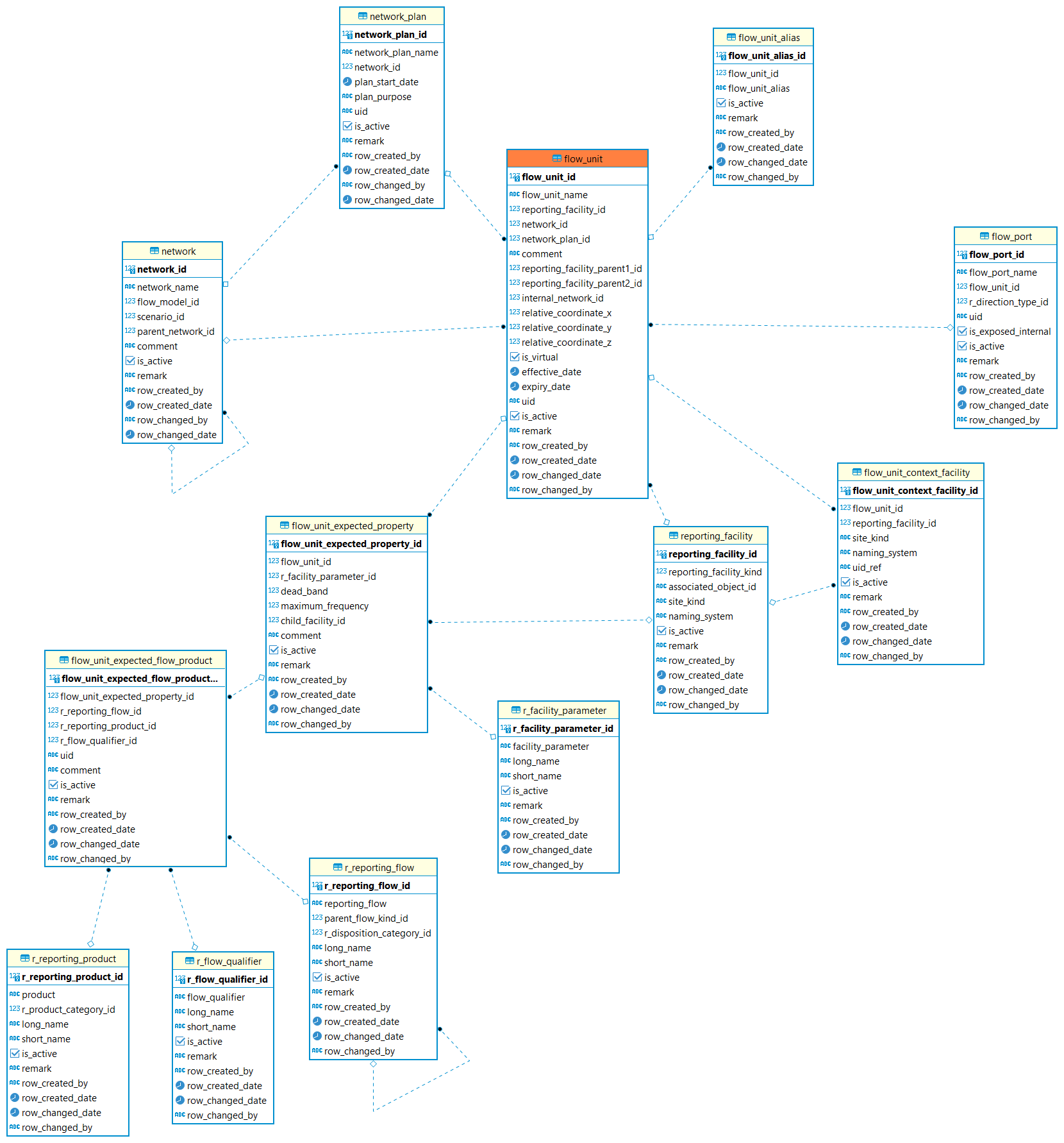
Flow unit needs to be linked to a specified network. One flow unit can represent one well or one facility. It depends on the network unit boundary. The reporting facility (label 1 in below picture) is the collection of all the entities that could be a unit. The relative coordinate xyz is used to define the relative position of the flow unit in the screen.
-
flow_Unit_alias is used to record the alias that used for this flow unit.
-
flow_unit_Context_facility is used to list the reporting facilities those are the context of the unit.
-
flow_Unit_expected_property is used to define expected properties of the facility represented by this unit.
-
flow_Unit_expected_product is used to define flow, such as product,flow kind and flow qualifier.
-
flow_Unit_nfp_tag_alias record an alternative name for the sensor that measures the property.
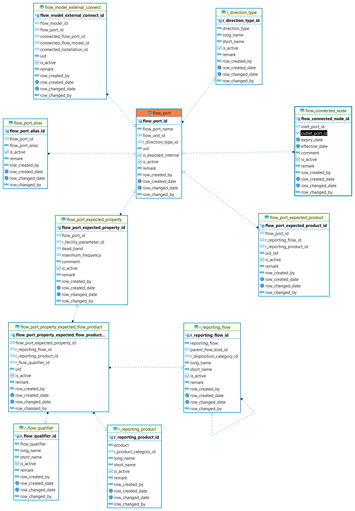
Flow Port
Flow port is used to record the product flow port associated with the product flow unit. It allows fluid flow in or out of one unit. Direction is needed for one port.
-
flow_Port_expected_product: Defines the expected flow and product pairs to be assigned to this port by a Product Volume report. A set of expected qualifiers can be defined for each pair.
-
flow_Port_expected_property: Defines the properties that are expected to be measured at this port.
-
flow_Port_expected_property_flow_product: Defines the flow,product and flow qualifier of the flow property.
-
flow_model_external_connection: The connection between different models can be connected by external ports.
The Expected Properties
When constructing a product flow model, it is important to differentiate between the Product'' type measurements (e.g., oil rate, gas rate, pressure etc.) which are reported at Ports. And the facility'' type measurements (e.g., motor speed, chock position, valve status, etc.) which can be measured and reported within a unit.
Information about a flow is best reported where it leaves or enters Units, which may modify the flow (e.g., separators, manifolds etc.). On the other hand, facility parameters are internal to the ``workings'' of a facility.
Tables Description
| Table | Description |
|---|---|
The non-contextual content of a product flow model data object. Model is a collection of networks. |
|
Identifies the context facilities of the model. |
|
Defines the external port in another Product Flow Model to which an external port in this model is connected. An external port should be connected to an external port with the opposite direction. The connected external port must be in another Product Flow Model. |
|
Identifies a entity this flow model represents for. |
|
Identifies a facility. |
|
The non-contextual content of a product flow network object. The network represents the internal behavior of the model or a unit in another network and is a collection of connected units. |
|
An external port. This exposes an internal node for the purpose of allowing connections to the internal behavior of the network. Networks that represent a Flow Unit should always have external ports. If this network represents a Unit, then the name of the external port must match the name of a port on the Unit (i.e., they are logically the same port). |
|
A plan to extend an actual network. |
|
Documents the point in time where network plan changes were made. |
|
Documents the point in time where network changes were made. |
|
Specify the scenario of the network. |
|
A flow unit is essentially a black box that can represent anything. Generally it is a kind of facility or well. |
|
The name of something within a naming system. This specifies flow unit alias. |
|
Identifies the context facilities of the UNIT. |
|
Defines expected properties of a facility represented by a unit. |
|
The name of something within a naming system. This specifies tag alias |
|
Defines an expected combination of kinds. |
|
Specifies the kinds of facility parameters. |
|
Flow ports allow fluid flow in or out of a flow unit. |
|
An alternative name of a port. |
|
Defines the expected flow and product pairs to be assigned to this port. |
|
Defines expected properties of a flow port. |
|
This specifies port tag alias |
|
Defines an expected combination of kinds. |
|
Nodes are used to connect ports. |